Bus Clipper
Introduction
A clipper is a type of dynamics processor designed to control peak level without time-dependent behavior such as attack or release. Unlike compressors and limiters, clipping happens instantly, making it ideal for managing transients without altering groove or punch.
Slate Digital Bus Clipper is a high-precision digital clipping tool aimed primarily at the mixing and mastering stages that occur near the end of the music production process; as such, it is aimed at mix and mastering engineers, though it might find some creative use by producers and songwriters in the earlier stages of song development.
It is intended to help increase overall loudness of mixes via two serial processing stages: a Clipper stage used to remove unnecessary or imperceptible transient spikes (thus allowing a subsequent increase of gain) followed by a Booster stage which employs waveshaping techniques to increase the loudness within the remaining signal.
Note: The following guide explains how to use the plugin. To learn more about the technical aspects and challenges we faced during the development of Bus Clipper, see this blog article. Happy reading!
Bus Clipper is included in the Complete Access subscription and is also available to users who have purchased a perpetual license through our Shop. You can install the plugin via the Complete Access Hub or by downloading the installer from our installers page.
Key Characteristics
Transparent Transient Control
Transients are short, wide-band events. When lightly clipped, their original harmonic content is largely replaced by similarly wide-band harmonics, which the ear often perceives as neutral, or even more impactful.
By shaving fast peaks, Bus Clipper creates additional headroom without changing perceived loudness. This allows you to push level higher while avoiding the pumping, smearing, or envelope artifacts often introduced by compressors or limiters. For this reason, Bus Clipper is ideal for mix buses and mastering chains.
Harmonic Generation
Clipping is a non-linear process, meaning the output is not a simple scaled version of the input. Flattening or curving waveform peaks introduces new harmonics, as the clipped waveform comes closer to a square wave. The shape of the clipping curve determines their character: smoother curves produce softer harmonics, while sharper curves generate stronger, higher-order harmonics.
Quick Start
-
Increase Input Gain: raise the input until clipping just starts to become audible, then back off slightly. At this point, fast transient peaks are being clipped, but tonal elements remain intact. Use the waveform display to confirm that only thin transient spikes are being affected.
-
Add Loudness with the Booster: increase the Booster Gain to raise overall level without introducing additional clipping. The Booster effectively lifts everything below the clipping ceiling, preserving the controlled transients from step one.
-
Protect the Output: reduce the output level or engage the True Peak Limiter (TPL) to prevent true peak overs.
Overview
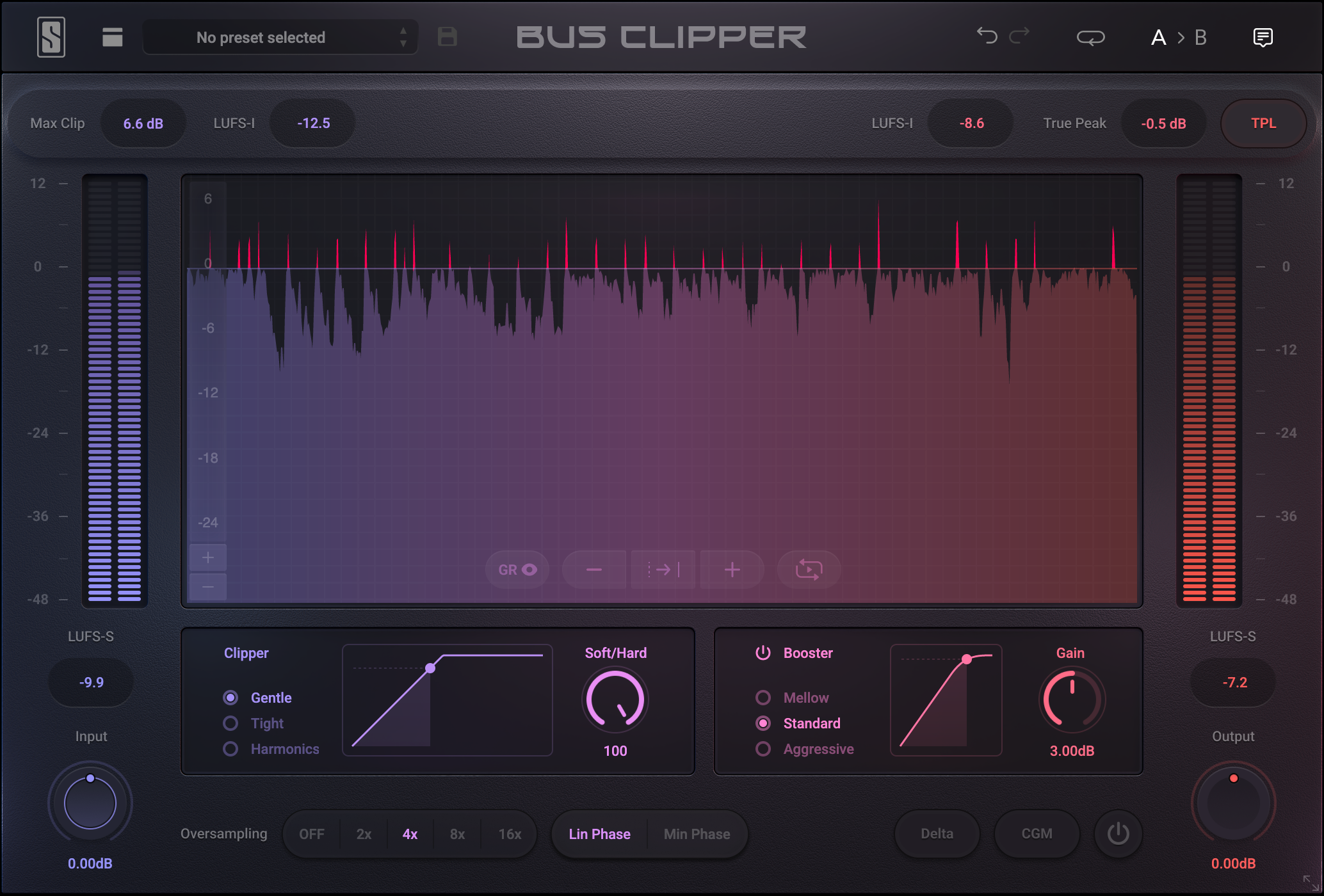
Bus Clipper is organized into the following sections:
-
Metering (top): Displays key information about loudness, maximum clipping amount, and peak levels.
-
Input (left): Adjusts the signal level entering the clipper
-
Clipping Functions (center): Comprised of two stages: Clipper and Booster, providing control over peak shaping and tonal character.
-
Waveform Display (middle): Visualizes input and output signals, the ceiling, and equivalent gain reduction in real time.
-
Output (right): Controls the signal level after clipping and boosting.
-
Additional Features (bottom): Includes Oversampling, Constant Gain Monitoring (CGM), and Bypass.
Metering
The Metering section provides all the information needed before exporting a track: peak values and Integrated Loudness (LUFS).
Loudness reflects the perceived volume of audio, taking into account human hearing characteristics. It is typically measured in LUFS (Loudness Units Full Scale) and is a key parameter for content platforms, ensuring a consistent listening experience. Mastering engineers carefully monitor this value during the mastering process.
Loudness is reported in three ways:
-
Max Clip: Shows the maximum dynamic range that was removed by the Clipper stage specifically. Gain changes created with the Booster stage are not included in this calculation.
-
Short-Term Loudness (LUFS-S): Average over the last 3 seconds (shown for both input and output)
-
Integrated Loudness (LUFS-I): Average of Short-Term Loudness across the entire track. Requires playback of the full track to calculate accurately.
True Peak Limiter (TPL)
In digital audio, waveform peaks can exceed the level between two consecutive samples, creating what are known as inter-sample peaks. On some systems, these inter-sample peaks can cause overload distortion when the digital signal is converted to analog. True Peak Limiting helps ensure inter-sample peaks do not exceed the ceiling.
The True Peak Limiter (TPL) in Bus Clipper complies with ITU-R BS.1770 and EBU R128 standards, using 4x oversampling at 44.1kHz and 48kHz and 2x oversampling at 96kHz and above, in order to estimate the level of inter-sample peaks.
Most streaming platforms recommend true peak ceiling of –1 dB TP. With TPL enabled, use the Output Trim to set the output to stay below the required true peak level.
Input
The Input Gain controls how hard the signal hits the clipping stages. This is the primary driver of transient control and harmonic generation.
PRO TIP: Hold the SHIFT key while adjusting the Input Gain to simultaneously apply the opposite amount of Output Gain. This can bring the waveform of low-level signals into view without changing the overall volume going through the Bus Clipper.
Clipper
The Clipper stage constrains the signal to a defined range set in combination with the Ceiling. The “Gentle” and “Tight” modes can have their shapes changed with the neighboring Soft/Hard knob, and the “Harmonics” mode allows for precise selection of odd-order harmonics.
Gentle Mode
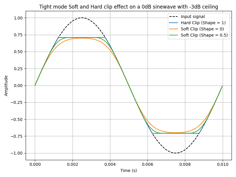
“Gentle” is the first of the soft-clipping shapes in the Clipper stage. The shape starts introducing gain changes at lower input levels compared to “Tight”. When turning the Soft/Hard knob counter-clockwise, this will apply more of this mode’s shape to the Clipper (as seen in the small graph display to the left of the Soft/Hard knob) which means gain changes will start happening before the level actually reaches the Ceiling. Conversely, turning the Soft/Hard knob clockwise will morph the Clipper’s shape towards a standard hard clipping shape which only affects signals that exceed the Ceiling (this creates the familiar “flat-top” waveform and generates strong, wide-band harmonics).
Tight Mode
“Tight” is the second soft-clipping shape in the Clipper stage. Compared to “Gentle”, above, the “Tight” shape waits to introduce gain changes until the signal reaches a higher level. As a result, more of the low-level signal will remain untouched while only the louder portions of the signal get reshaped by the Clipper.
The Soft/Hard knob morphs between the original “Tight” shape (knob fully counter-clockwise) and will morph to the standard hard clipping shape as the knob is turned clockwise.
Hard Clipping
To achieve the classic hard clipping shape, use either the “Gentle” or “Tight” mode and turn the Soft/Hard knob fully clockwise. The resulting hard clipping shape is identical for both modes.
Because everything below the ceiling remains untouched, hard clipping is the most transparent option for simply shaving transients, especially in mastering.
Harmonics Mode
When using the “Harmonics” mode, you can specify the number of odd-order harmonics that will be generated upon clipping. Simply use the Harmonics knob to select between 3 and 21 overtones. For example, setting the Harmonics knob to “7” will add 3rd, 5th, and 7th order harmonics when clipping.
Booster
The Booster is a specialized form of soft clipping where the gain (slope) of the transfer function is increased without exceeding the maximum amplitude. This is why the Booster is placed after the initial Clipper stage.
The Booster curves are specifically designed to maximize level increase without actually increasing the peak level. This often makes it possible to simply make the signal louder without aggressively increasing harmonic artifacts.
In practice, the Clipper is used first to control fast transient peaks, up to the point where clipping distortion starts to become noticeable. Once those peaks are under control, the Booster can be used to increase overall loudness more cleanly.
As a general guideline, using 2 dB of clipping followed by 2 dB of Booster gain will typically sound cleaner and more transparent than applying 4 dB of clipping alone.
Oversampling
Digital audio is limited by the Nyquist frequency, which is equal to half the session’s sample rate. Frequencies above this limit cannot be represented accurately and will fold back into the audible range as aliasing artifacts.
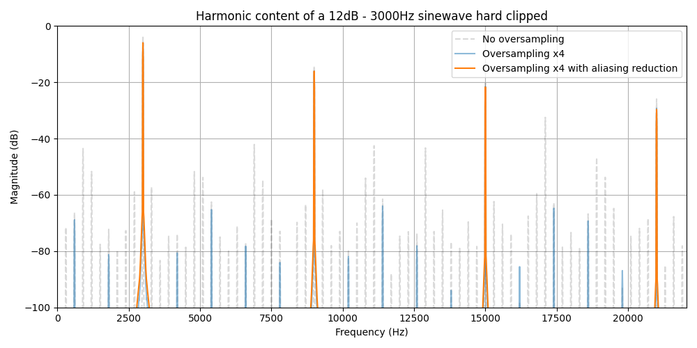
Clipping is particularly prone to creating aliasing because it generates strong, wide-band harmonics that extend far above the original frequency content of the signal. If these harmonics exceed the Nyquist limit, they fold back into the audible range, often perceived as harshness or brittle distortion—especially noticeable in high-frequency material and during heavy clipping.
Oversampling temporarily increases the sample rate inside Bus Clipper before the clipping process actually takes place. This provides additional frequency bandwidth so that the harmonics generated by clipping can form naturally in the ultrasonic range.
After clipping:
-
A low-pass filter removes ultrasonic content
-
The signal is downsampled back to the session’s original sample rate
Because the ultrasonic harmonics are filtered out before downsampling, aliasing artifacts are significantly reduced or completely avoided when converting back to the original project sample rate.
Higher oversampling settings provide more headroom for harmonic generation and better alias suppression, at the cost of increased CPU usage and latency. If your CPU struggles at high Oversampling settings, you can use low oversampling settings when just making the initial settings for Bus Clipper, then enable a high setting before doing your final offline render/export.
Finally, Bus Clipper features built-in aliasing reduction, making its oversampling more effective than standard oversampling methods.
Linear Phase vs Minimum Phase
When using Oversampling, a low-pass filter must be used to remove ultrasonic frequencies before downsampling. Bus Clipper offers two filter types to use before downsampling, each with a different sonic tradeoff:
-
Linear Phase preserves phase accuracy across the entire frequency spectrum to maintain. Introduces latency and may produce subtle pre-ringing.
-
Minimum Phase: Introduces phase shift at very high frequencies, which can increase the peak level. Reduce pre-ringing and latency.
Constant Gain Monitoring (CGM)
CGM automatically compensates output level for any gain added by the Input control and Booster. This allows instant, level-matched A/B comparisons when toggling bypass, so you hear what Bus Clipper is doing to the actual shape of the audio, without being distracted by how much louder it is. It can be easier to judge if too many harmonics and distortions are being added when doing A/B comparisons with GCM enabled.
Gain Reduction Visualizer (GR)
Clicking the GR button on the waveform display will show or hide the equivalent gain reduction being applied to the entire audio being processed by the plug-in. It not only shows the gain reduction resulting from the levels clipped by the Clipper stage, but also includes the equivalent gain reduction that is caused by the Booster stage and the True Peak Limiter in order to provide a total gain reduction value. This GR visualization is aligned with the scale on the left side of the waveform display.